1. Raspberry Pi as a Router Using a Single Network Interface

    Wed 29 September 2021

    Introduction

    Disclaimer: this article is intended for consumers and hobbyists.


    If you want to run your own router at home, the Raspberry Pi 4 Model B1 can be an excelent hardware choice:

    1. it's fairly cheap
    2. it's fast enough
    3. it can saturate it's gigabit network port
    4. it is power-efficient

    The key problem it seems, is that it has only one, single network interface. If you build a router, you need at least two:

    1. The first interface connected to your internet modem/router (ideally in bridge mode)
    2. The second interface connected to your home network (probably a switch)

    So if you would use the Raspberry Pi, you would probably buy a gigabit USB3 NIC for around $20 and be done with it.
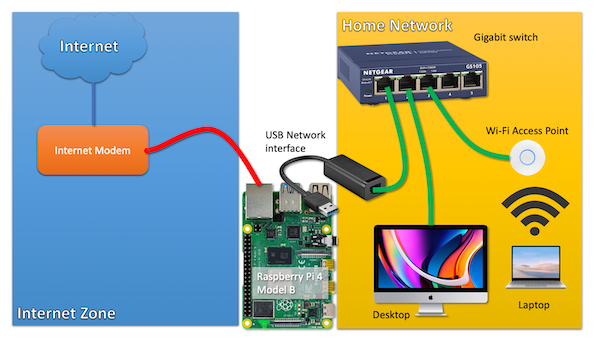
    routersetup click on the image for a larger version

    Now, what if I told you that you can build exactly the same setup by using only the single on-board network interface of the Raspberry Pi 4?

    How is that possible?

    Introducing VLANs

    Yes, I'm introducing the reader to a technology that exists since the '90s. It is widely used within businesses and other organisations.

    Because I have a sense that this technology is less well-known in circles outside IT operations, I think it may be an interesting topic to discuss.

    Understanding VLANs

    VLAN technology allows you to run different, separate networks over the same, single physical wire and on the same, single switch. This saves a lot on network cabling and the number of physical switches required if you want to operate networks that are separate from each other.

    If you want to run traffic from different networks over the same physical wire or switch, how can you identify those different traffic flows?

    With VLAN technology enabled, such network 'packets' are labeled with a tag. As the VLAN technology operates at the level of Ethernet, we should not talk about 'packets' but about 'ethernet frames'. The terminology is not important to understand the concept, I think.

    It suffices to understand that there is a tag put in front of the ethernet frame, that tells any device that supports VLANs to which network a frame and thus a packet belongs.

    This way, network traffic flows, can be distinguished from each other. And those tags are nothing fancy, they are called a VLAN ID and it is just a number between 1 and 40962.

    Managed switch

    Now that we understand the concept of VLANs, how do we use it?

    First of all, you need a managed network switch that supports VLANs.

    The cheapest switch with VLAN support I could find is the TP-LINK TL-SG105E, for around 25 euros or dollars. This is a 5-port switch, but the 8-port version is often only a few euros/dolars more.


    Juan Pedro Paredes in the comments point out that this TP-LINK switch may not be able to handle the large number of ARP requests that may arrive at the port connected to the Internet Modem. Others are quite negative about this switch in the Hacker News discussion (linked below). I'm not sure if Netgear switches, which are near the same price, fare any better.


    A switch like this has a web-based management interface that allows you to configure VLANS on the device.

    Tagged vs untagged

    In the context of VLANS, a network switch port can be in two states:

    1. Member of a particular network (VLAN) (untagged)
    2. Transporting multiple networks (VLANs) (tagged)

    If a port is just a member of a VLAN, it just behaves like any other switch port. In this mode, it can obviously only be a member of one network/VLAN. The VLAN tags are stripped off all network traffic coming out of this port.

    However, a port that is assigned 'tagged' VLAN trafic, just forwarded traffic as-is, including their VLAN tag.

    This is the trick that we use to send network packets from different networks (VLANS) to our Raspberry Pi router over a single port/wire.
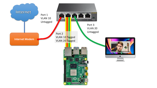
    routersetup click on the image for a larger version

    So let's unpack this picture together, step by step.

    Let's imagine a (return) packet from the Internet arrives at the modem and is sent into switchport 1.

    The switch knows that any traffic on that switch port belongs to VLAN 10. Since this traffic needs to be send towards the Pi Router, it will put a tag on the packet and forwards the packet, including the tag towards the Pi on switch port 2.

    The Pi - in turn - is configured to work with VLANs just as the switch. The tag on the packet tells the Pi to wich virtual interface the packet must be send.

    A netplan configuration example to illustrate this setup:

    network:
      version: 2
      ethernets:
        enp2s0f0:
          dhcp4: no
      vlans:
        enp2s0f0.10:
           id: 10
           link: enp2s0f0
           addresses:
             - 68.69.70.71/24 (fake internet address)
           gateway4: 68.69.70.1 (fake upstream ISP router)
        enp2s0f0.20:
           id: 20
           link: enp2s0f0
           addresses:
             - 192.168.0.1/24 (internal network address, acting as gateway)
    

    As you can see, the VLAN packets that arrive as tagged packets, are send (without their tags) to a virtual network interface belonging to that particular network. Those virtual network interfaces all share the same physical interface (enp2s0f0). The virtual network interfaces are just the physical interface name with ".(VLAN ID)" added.

    From here on out, you probably understand where this is going: those two virtual network interfaces are basically similar to a setup with two physical network interfaces. So all the routing and NAT that needs to happen, just happens on those two virtual interfaces instead.

    How to work with VLANs

    To work with VLANs, you need a managed switch that supports VLANs. A managed switch has a management interface, often a web-based management interface.

    In this example, I'm using the TP-LINK TL-SG105E switch as an example. To get to this page, go to VLAN --> 802.1Q VLAN in the web interface.

    vlanconfig

    So from this table we can derive that:

    • Port 1 is an untagged member of VLAN 10
    • Port 2 is a tagged member of VLAN 10 and VLAN 20
    • Port 3 is an untagged member of VLAN 20

    Please note that it is also recommended to remove ports from VLANs they don't use. So I removed ports 1, 2 and 3 from the default VLAN 1.

    Now, if you have more devices to connect to the internal LAN on this switch, you need to configure the ports to be an untagged member of VLAN 20.

    Caveats

    Bandwidth impact

    Obviously, if you use a single interface, you only get to use the bandwidth of that sinle interface. In most cases, this is not an issue, as gigabit ethernet is full-duplex: there is physical exclusive wiring for upstream traffic and downstream traffic.

    So you might say that full-duplex gigabit ethernet has a raw throughput capacity of two gigabit/s, although we mostly don't talk about it that way.

    So when you download at 200 Mbit/s, that traffic is ingested over VLAN 10 over the incomming traffic path. It is then sent out over VLAN 20 towards your computer over VLAN 20 using the outgoing path. No problem there.

    If you would also use the Raspberry Pi as a backup server (with an attached external hard drive), the backup traffic and the internet traffic could both 'fight' for bandwidth on the same gigabit link.

    Impact on gigabit internet


    Update June 2022 I was actually able to use full Gigabit internet speed over VLANs, at around 111 MB/s. I made some mistakes during earlier testing.

    You will never get the full gigabit internet network speed if you would build this setup. It will probably max out at ~900 Mbit. (I'm assuming here that you would use x86 hardware as the Pi would not be able to handle firewalling this traffic anyway.)


    This is because most traffic is based on TCP connections and when you download, there is traffic both ways!. The download traffic is the bulk of the traffic, but there is a substantial steady stream of return packets that acknowledges to the sender that traffic has been received (if not, it would trigger a retransmission).

    Remember that in this single-port setup, the Pi uses the same gigabit port to send the return traffic to the internet over VLAN 10 and the download data towards your home computer over VLAN 20. So the size of the upstream traffic will limit your maximum download performance.

    The Raspberry Pi 4 Model B as a router

    The biggest limitation - which becomes an issue for more and more people - is performance. If you use IPTABLES on Linux for firewalling, in my experience, network throughput drops to a maximum of 650 Mbit/s.

    That's only an issue (first world problems) if you have gigabit internet or an internet speed beyond what the Pi can handle.

    If your internet speed doesn't even come close, this is not an issue at all.

    Maybe the Raspberry Pi 400 or the compute module performs better in this regard as their CPUs are clocked at higher Ghz.

    Closing words

    If it makes any sense for you to implement this setup, is only for you to decide. I'm running this kind of setup (using an x86 server) for 10 years as I can't run a second cable from my modem to the room where my router lives. For a more detailed picture of my home network setup, take a look here.

    Feel free to leave any questions of comments below.

    The hacker news discussion about this article can be found here.

    Route-on-a-stick

    I learned from the hacker news discussion that a router with just one network interface is called a router on a stick.


    1. Older models of the Raspberry Pi are significantly network bandwidth constrained. So much so, that they would not be suitable as Internet routers if your internet speed is above 100Mbit. 

    2. most cheap switches can't operate more than 32 ~ 64 VLANs maximum. Only more expensive, enterprise gear can work with the full 4096 VLANS at the same time. However, this is probably not relevant for consumers. 

    Tagged as : networking
  2. My Home Network Setup Based on Managed Switches and VLANs

    Fri 10 April 2020

    My home networking setup

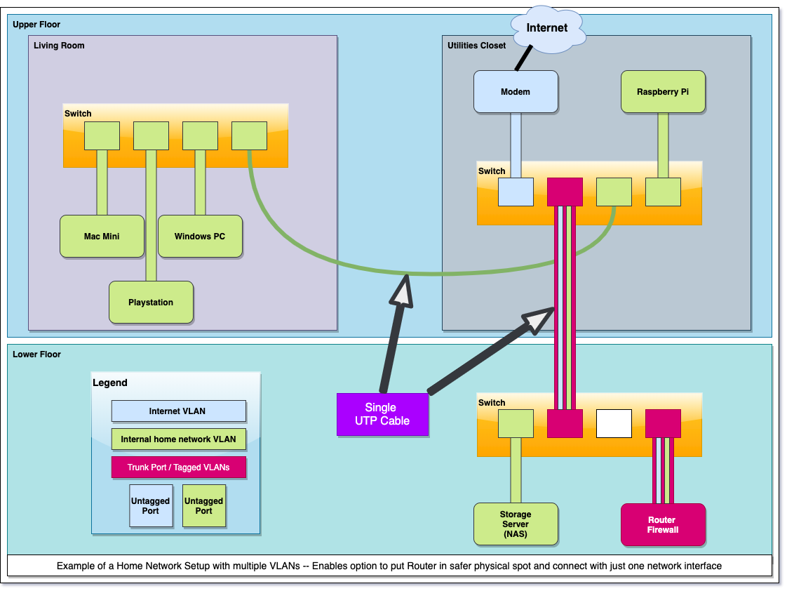
    I live in a two story apartment, with on the top floor my utilities closet and my living room. The bottom floor contains a bedroom with all my servers and networking gear.

    So this is my setup (click for a bigger version):

    home

    I like to run my own router but my utilities closed is not the safest place in terms of security and climate.

    By default, most people who run their own home router will use a box with two network interfaces, one connected to the (cable) modem and the other one connected to the home network.

    I could have done the same thing, by running a cable from the modem to my router, and a second cable back up towards my closet (and livingroom).

    However, I didn't want to run multiple cables from my utilities closed to my bedroom downstairs, I saw no need for that: because I can use VLANs.

    The small 8-port switch in the closed is connected with a single (long) cable to the 24-port switch I have in my bedroom downstairs. This switch connects to my router and multiple servers.

    I've setup a trunk between these two switches where my internet traffic flows over 'VLAN 100' and my home network uses 'VLAN 200'.

    The router, an HP N40L, has only a single network interface. I just expose the two VLANS as 'tagged' and let the router route traffic between the two VLANS. No need for a second interface (as many home setups do).

    So in my setup there are two trunks, one between the two switches and the other one between the bedroom switch and my router. All other devices are connected to untagged network ports, in their appropriate VLAN.

    The small switch in the closet is responsible for carrying my home network to the switch in my living room.

    The raspberry pi connects to my smart meter to collect information about my power and gas usage.

    Tagged as : Networking
  3. HP Proliant Microserver Gen10 as Router or NAS

    Thu 14 September 2017

    Introduction

    In the summer of 2017, HP released the Proliant Microserver Gen10. This machine replaces the older Gen8 model.

    gen10

    For hobbyists, the Microserver always has been an interesting device for a custom home NAS build or as a router.

    Let's find out if this is still the case.

    Price

    In The Netherlands, the price of the entry-level model is similar to the Gen8: around €220 including taxes.

    CPU

    The new AMD X3216 processor has slightly better single threaded performance as compared to the older G1610t in the Gen8. Overall, both devices seem to have similar CPU performance.

    The biggest difference is the TDP: 35 Watt for the Celeron vs 15 Watt for the AMD CPU.

    Memory

    By default, it has 8 GB of unbuffered ECC memory, that's 4 GB more than the old model. Only one of the two memory slots is occupied, so you can double that amount just by adding another 8 GB stick. It seems that 32 GB is the maximum.

    Storage

    This machine has retained the four 3.5" drive slots. There are no drive brackets anymore. Before inserting a hard drive, you need to remove a bunch of screws from the front of the chassis and put four of them in the mounting holes of each drive. These screws then guide the drive through grooves into the drive slot. This caddy-less design works perfectly and the drive is mounted rock-solid in it's position.

    To pop a drive out, you have to press the appropriate blue lever, which latches on to one of the front screws mounted on your drive and pulls it out of the slot.

    There are two on-board sata controllers.

    00:11.0 SATA controller: Advanced Micro Devices, Inc. [AMD] FCH SATA Controller [AHCI mode] (rev 49)
    01:00.0 SATA controller: Marvell Technology Group Ltd. 88SE9230 PCIe SATA 6Gb/s Controller (rev 11)
    

    The Marvell controller is connected to the four drive bays. The AMD controller is probably connected to the fifth on-board SATA port.

    As with the Gen8, you need a floppy-power-connector-to-sata-power-connector cable if you want to use a SATA drive with the fifth onboard SATA port.

    Due to the internal SATA header or the USB2.0 header, you could decide to run the OS without redundancy and use all four drive bays for storage. As solid state drives tend to be very reliable, you may use a small SSD to keep the cost and power usage down and still retain reliability (although not the level of reliability RAID1 provides).

    Networking

    Just as the Gen8, the Gen10 has two Gigabit network cards. The brand and model is: Broadcom Limited NetXtreme BCM5720

    As tested with iperf3 I get full 1 Gbit network performance. No problems here (tested on CentOS 7).

    PCIe slots

    This model has two half-height PCIe slots (1x and 8x in a 4x and 8x physical slot) which is an improvement over the single PCIe slot in the Gen8.

    USB

    The USB configuration is similar to the Gen8, with both USB2 and USB3 ports and one internal USB2 header on the motherboard.

    Sidenote: the onboard micro SD card slot as found in the Gen8 is not present in the Gen10.

    Graphics

    The Gen10 has also a GPU build-in but I have not looked into it as I have no use for it.

    The Gen10 differs in output options as compared to the Gen8: it supports one VGA and two displayport connections. Those displayport connectors could make the Gen10 an interesting DIY HTPC build, but I have not looked into it.

    iLO

    The Gen10 has no support for iLO. So no remote management, unless you have an external KVM-over-IP solution.

    This is a downside, but for home users, this is probably not a big deal. My old Microserver N40L didn't have iLO and it never bothered me.

    And most of all: iLO is a small on-board mini-comuter that increases idle power consumption. So the lack of iLO support should mean better idle power consumption.

    Boot

    Both Legacy and UEFI boot is supported. I have not tried UEFI booting.

    Booting from the 5th internal SATA header is supported and works fine (as opposed to the Gen8).

    For those who care: booting is a lot quicker as opposed to the Gen8, which took ages to get through the BIOS.

    Power Usage

    I have updated this segment as I have used some incorrect information in the original article.

    The Gen10 seems to consume 14 Watt at idle, booted into Centos 7 without any disk drives attached (removed all drives after booting). This 14 Watt figure is reported by my external power meter.

    Adding a single old 7200 1 TB drive drives power usage up to 21 Watt (as expected).

    With four older 7200 RPM drives the entire system uses about 43 Watt according to the external power meter.

    As an experiment, I've put two old 60 GB 2.5" laptop drives in the first two slots, configured as RAID1. Then I added two 1 TB 7200 RPM drives to fill up the remaining slots. This resulted in a power usage of 32 Watt.

    Dimensions and exterior

    Exactly the same as the Gen8, they stack perfectly.

    The Gen8 had a front door protecting the drive bays connected to the chassis with two hinges. HP has been cheap on the Gen10, so when you open the door, it basically falls off, there's no hinge. It's not a big issue, the overall build quality of the Gen10 is excellent.

    I have no objective measurements of noise levels, but the device seems almost silent to me.

    Evaluation and conclusion

    At first, I was a bit disappointed about the lack of iLO, but it turned out for the best. What makes the Gen10 so interesting is the idle power consumption. The lack of iLO support probably contributes to the improved idle power consumption.

    The Gen8 measures between 30 and 35 Watt idle power consumption, so the Gen10 does fare much better (~18 Watt).

    Firewall/Router

    At this level of power consumption, the Gen10 could be a formidable router/firewall solution. The only real downside is it's size as compared to purpose-built firewalls/routers. The two network interfaces may provide sufficient network connectivity but if you need more ports and using VLANs is not enough, it's easy to add some extra ports.

    If an ancient N40L with a piss-poor Atom processor can handle a 500 Mbit internet connection, this device will have no problems with it, I'd presume. Once I've taken this device into production as a replacement for my existing router/firewall, I will share my experience.

    Storage / NAS

    The Gen8 and Gen10 both have four SATA drive bays and a fifth internal SATA header. From this perspective, nothing has changed. The reduced idle power consumption could make the Gen10 an even more attractive option for a DIY home grown NAS.

    All things considered I think the Gen10 is a great device and I have not really encountered any downsides. If you have no problems putting a bit of effort into a DIY solution, the Gen10 is a great platform for a NAS or Router/Firewall, that can compete with most purpose-build devices.

    I may update this article as I gain more experience with this device.

    Tagged as : Storage Networking

Page 1 / 2