Introduction
Disclaimer: this article is intended for consumers and hobbyists.
If you want to run your own router at home, the Raspberry Pi 4 Model B1 can be an excelent hardware choice:
- it's fairly cheap
- it's fast enough
- it can saturate it's gigabit network port
- it is power-efficient
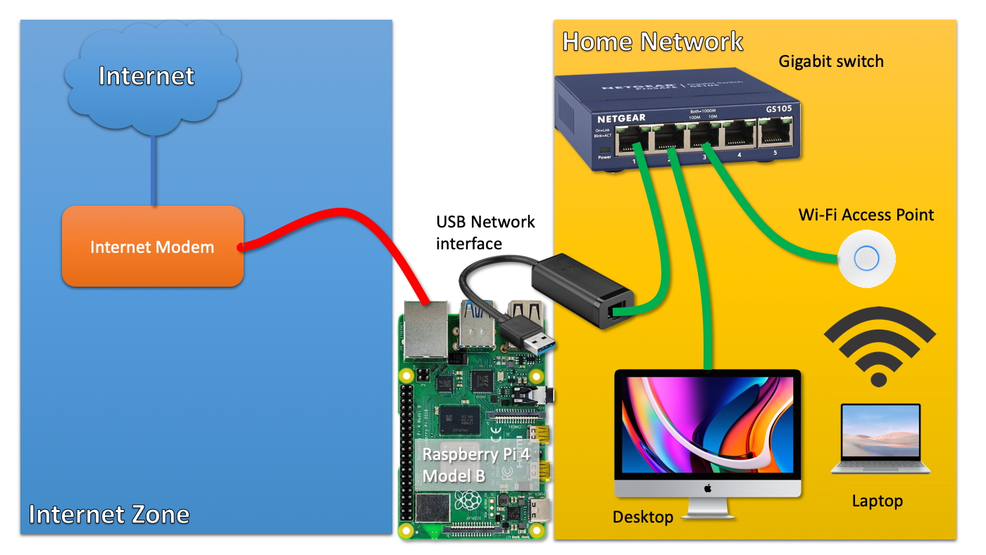
The key problem it seems, is that it has only one, single network interface. If you build a router, you need at least two:
- The first interface connected to your internet modem/router (ideally in bridge mode)
- The second interface connected to your home network (probably a switch)
So if you would use the Raspberry Pi, you would probably buy a gigabit USB3 NIC for around $20 and be done with it.
 click on the image for a larger version
Now, what if I told you that you can build exactly the same setup by using only the single on-board network interface of the Raspberry Pi 4?
How is that possible?
Introducing VLANs
Yes, I'm introducing the reader to a technology that exists since the '90s. It is widely used within businesses and other organisations.
Because I have a sense that this technology is less well-known in circles outside IT operations, I think it may be an interesting topic to discuss.
Understanding VLANs
VLAN technology allows you to run different, separate networks over the same, single physical wire and on the same, single switch. This saves a lot on network cabling and the number of physical switches required if you want to operate networks that are separate from each other.
If you want to run traffic from different networks over the same physical wire or switch, how can you identify those different traffic flows?
With VLAN technology enabled, such network 'packets' are labeled with a tag. As the VLAN technology operates at the level of Ethernet, we should not talk about 'packets' but about 'ethernet frames'. The terminology is not important to understand the concept, I think.
It suffices to understand that there is a tag put in front of the ethernet frame, that tells any device that supports VLANs to which network a frame and thus a packet belongs.
This way, network traffic flows, can be distinguished from each other. And those tags are nothing fancy, they are called a VLAN ID and it is just a number between 1 and 40962.
Managed switch
Now that we understand the concept of VLANs, how do we use it?
First of all, you need a managed network switch that supports VLANs.
The cheapest switch with VLAN support I could find is the TP-LINK TL-SG105E, for around 25 euros or dollars. This is a 5-port switch, but the 8-port version is often only a few euros/dolars more.
Juan Pedro Paredes in the comments point out that this TP-LINK switch may not be able to handle the large number of ARP requests that may arrive at the port connected to the Internet Modem. Others are quite negative about this switch in the Hacker News discussion (linked below). I'm not sure if Netgear switches, which are near the same price, fare any better.
A switch like this has a web-based management interface that allows you to configure VLANS on the device.
Tagged vs untagged
In the context of VLANS, a network switch port can be in two states:
- Member of a particular network (VLAN) (untagged)
- Transporting multiple networks (VLANs) (tagged)
If a port is just a member of a VLAN, it just behaves like any other switch port. In this mode, it can obviously only be a member of one network/VLAN. The VLAN tags are stripped off all network traffic coming out of this port.
However, a port that is assigned 'tagged' VLAN trafic, just forwarded traffic as-is, including their VLAN tag.
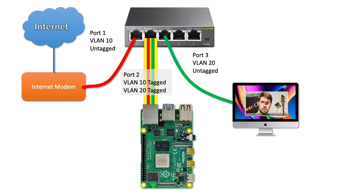
This is the trick that we use to send network packets from different networks (VLANS) to our Raspberry Pi router over a single port/wire.
 click on the image for a larger version
So let's unpack this picture together, step by step.
Let's imagine a (return) packet from the Internet arrives at the modem and is sent into switchport 1.
The switch knows that any traffic on that switch port belongs to VLAN 10. Since this traffic needs to be send towards the Pi Router, it will put a tag on the packet and forwards the packet, including the tag towards the Pi on switch port 2.
The Pi - in turn - is configured to work with VLANs just as the switch. The tag on the packet tells the Pi to wich virtual interface the packet must be send.
A netplan configuration example to illustrate this setup:
network:
  version: 2
  ethernets:
    enp2s0f0:
      dhcp4: no
  vlans:
    enp2s0f0.10:
       id: 10
       link: enp2s0f0
       addresses:
         - 68.69.70.71/24 (fake internet address)
       gateway4: 68.69.70.1 (fake upstream ISP router)
    enp2s0f0.20:
       id: 20
       link: enp2s0f0
       addresses:
         - 192.168.0.1/24 (internal network address, acting as gateway)
As you can see, the VLAN packets that arrive as tagged packets, are send (without their tags) to a virtual network interface belonging to that particular network. Those virtual network interfaces all share the same physical interface (enp2s0f0). The virtual network interfaces are just the physical interface name with ".(VLAN ID)" added.
From here on out, you probably understand where this is going: those two virtual network interfaces are basically similar to a setup with two physical network interfaces. So all the routing and NAT that needs to happen, just happens on those two virtual interfaces instead.
How to work with VLANs
To work with VLANs, you need a managed switch that supports VLANs. A managed switch has a management interface, often a web-based management interface.
In this example, I'm using the TP-LINK TL-SG105E switch as an example. To get to this page, go to VLAN --> 802.1Q VLAN in the web interface.
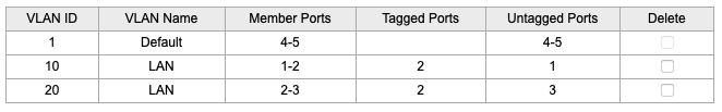
So from this table we can derive that:
- Port 1 is an untagged member of VLAN 10
- Port 2 is a tagged member of VLAN 10 and VLAN 20
- Port 3 is an untagged member of VLAN 20
Please note that it is also recommended to remove ports from VLANs they don't use. So I removed ports 1, 2 and 3 from the default VLAN 1.
Now, if you have more devices to connect to the internal LAN on this switch, you need to configure the ports to be an untagged member of VLAN 20.
Caveats
Bandwidth impact
Obviously, if you use a single interface, you only get to use the bandwidth of that sinle interface. In most cases, this is not an issue, as gigabit ethernet is full-duplex: there is physical exclusive wiring for upstream traffic and downstream traffic.
So you might say that full-duplex gigabit ethernet has a raw throughput capacity of two gigabit/s, although we mostly don't talk about it that way.
So when you download at 200 Mbit/s, that traffic is ingested over VLAN 10 over the incomming traffic path. It is then sent out over VLAN 20 towards your computer over VLAN 20 using the outgoing path. No problem there.
If you would also use the Raspberry Pi as a backup server (with an attached external hard drive), the backup traffic and the internet traffic could both 'fight' for bandwidth on the same gigabit link.
Impact on gigabit internet
Update June 2022 I was actually able to use full Gigabit internet speed over VLANs, at around 111 MB/s. I made some mistakes during earlier testing.
You will never get the full gigabit internet network speed if you would build this setup. It will probably max out at ~900 Mbit. (I'm assuming here that you would use x86 hardware as the Pi would not be able to handle firewalling this traffic anyway.)
This is because most traffic is based on TCP connections and when you download, there is traffic both ways!. The download traffic is the bulk of the traffic, but there is a substantial steady stream of return packets that acknowledges to the sender that traffic has been received (if not, it would trigger a retransmission).
Remember that in this single-port setup, the Pi uses the same gigabit port to send the return traffic to the internet over VLAN 10 and the download data towards your home computer over VLAN 20. So the size of the upstream traffic will limit your maximum download performance.
The Raspberry Pi 4 Model B as a router
The biggest limitation - which becomes an issue for more and more people - is performance. If you use IPTABLES on Linux for firewalling, in my experience, network throughput drops to a maximum of 650 Mbit/s.
That's only an issue (first world problems) if you have gigabit internet or an internet speed beyond what the Pi can handle.
If your internet speed doesn't even come close, this is not an issue at all.
Maybe the Raspberry Pi 400 or the compute module performs better in this regard as their CPUs are clocked at higher Ghz.
Closing words
If it makes any sense for you to implement this setup, is only for you to decide. I'm running this kind of setup (using an x86 server) for 10 years as I can't run a second cable from my modem to the room where my router lives. For a more detailed picture of my home network setup, take a look here.
Feel free to leave any questions of comments below.
The hacker news discussion about this article can be found here.
Route-on-a-stick
I learned from the hacker news discussion that a router with just one network interface is called a router on a stick.
-
Older models of the Raspberry Pi are significantly network bandwidth constrained. So much so, that they would not be suitable as Internet routers if your internet speed is above 100Mbit. ↩
-
most cheap switches can't operate more than 32 ~ 64 VLANs maximum. Only more expensive, enterprise gear can work with the full 4096 VLANS at the same time. However, this is probably not relevant for consumers. ↩
Comments